
ACTIVE FLOW CONTROL ON AIRFRAME (TS2, TS3)
Main expected results:
Experimental demonstration of locally applied active flow control technologies for performance increase and/or loads control
Progress so far:
JANUARY 2016
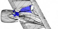
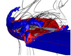
Active flow control technologies are being developed by a consortium of 18 partners targeting to recover performance issues of novel aircraft configurations in aerodynamically sensitive regions. Two challenges are addressed: i) large nacelles of Ultra High Bypass Ratio turbofans come with the risk of flow separation, thus performance deficit at wing/pylon junction ii) large span wings with aggressively designed wing tip could contain flow separation at the wing tip thus increased drag.
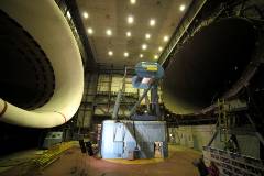
Recently, a Preliminary Design Review took place with support from an industrial expert panel judging the flow control concept for the wing pylon area, focusing on two axes: flow control with and without air net mass flux. Current ground testing aiming to verify the performance and functionalities of flow control hardware supported by numerical simulations will prepare the next Critical Design Review (2016). In parallel the design of interfaces between flow control hardware and the wind tunnel model is on-going, key players being the hardware designers and the tunnel operator.
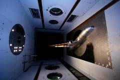
For the second technical challenge of performance deficits at outer wing, numerical simulations (CFD) were carried out following the requirements from aerodynamic and hardware designs.These requirements include jet actuation velocities, actuation width, length and spacing. It turns out that current hardware concepts face problems to deliver the required peak velocities. In parallel flow control robustness and environmental ground testing is being prepared by INCAS, aiming to execute them in the last project year. The partner TAU will do an aerodynamic validation of flow control technology applied to a generic configuration via dedicated wind tunnel testing.
APRIL 2015
- Minimisation of performance deficits due to locally separated areas, such as:
- wing/pylon junction when integrating upcoming UHBR engines;
- the outer part of an “aggressive” wing-tip extension in the vicinity of the missing slat. - Completion of the CFD computations for baseline configurations while dealing with challenging baseline geometries
- Investigation of the aerodynamic effectiveness of pulsed and synthetic jets emerging through circular holes or slot outlets
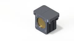
- Constant updates of the AFC hardware developments in close collaboration with the CFD partners
- Start of the preparation of the complementary tests (wind tunnel, laboratory and ground demonstration tests) to achieve TRL 3-4 for the technology demonstration.
JULY 2014
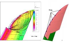
- Definition of the baseline configurations (FNG and XRF1 models) and flow conditions for carrying out numerical simulations.
- Delivery of baseline geometries.
- State-of-the-art survey of related AFC concepts.
- Provision of initial requirements for AFC technology, as well as the very first aspects of actuator integration.
- The reference a/c FNG model, considered for CFD (cf. ), will be represented by the SADE model (cf. Figure WP2-2) for technology readiness testing in Wind Tunnel.
 Preparation of a DMU of the SADE Wind Tunnel model, to ease the cooperation between partners dealing with AFC hardware integration.
JANUARY 2014
 Industrial requirements provided, to be completed with the Comprehensive numerically studies in terms of optimal actuator characteristics (position, hole, slot, flow rate, pulsed frequency…)
- Definition of the baseline configuration, the aerodynamic characterization of the baseline flow (cf. Fig. ) and some first actuator integration studies: pulsed jet with net mass flux, pulsed jet without net mass flux (i.e. synthetic jet) or suction & oscillatory blowing actuators.
- Preparation of laboratory ground tests devoted to the assessment of AFC actuators robustness in harsh environment and of wind tunnel tests to asses
 s the aerodynamic efficiency of such actuators.
